


BSS138 N-Channel MOSFET – Specifications, Pinout, and Circuit
Introduction
BSS138 is a small N-channel MOSFET used for low-voltage switching and logic level shifting, especially between 3.3V and 5V systems.
Specifications
Type: N-Channel Enhancement Mode
Package: SOT-23
Applications: General-purpose switching, level shifting
Maximum Ratings (at 25°C):
-
VDS (Drain-Source Voltage): 50 V
-
VGS (Gate-Source Voltage): ±20 V
-
ID (Continuous Drain Current): 200 mA
-
IDM (Pulsed Drain Current): 800 mA
-
PD (Power Dissipation): 310 mW
-
TJ, Tstg (Operating/Storage Temp): -55°C to +150°C
Thermal Resistance:
-
RθJA: 400 °C/W
Electrical Characteristics (Typical at 25°C):
-
VGS(th) (Gate Threshold Voltage): 0.8–1.5 V
-
RDS(on) at VGS = 4.5 V: ~3.5 Ω
-
RDS(on) at VGS = 10 V: ~2.5 Ω
-
IDSS (Off-State Leakage): ≤1 µA
-
Ciss (Input Capacitance): ~50–75 pF
BSS138 MOSFET Pinout
The BSS138 has three pins: Gate, Source, and Drain, each serving a specific switching function.
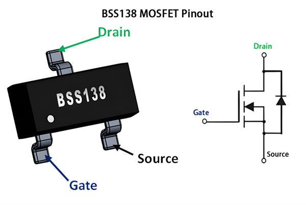
Pin Configuration
-
Gate (Pin 1): Input control pin. Apply 2–10V to turn the MOSFET on. Works with 3.3V or 5V logic.
-
Source (Pin 2): Connect to ground in low-side switching.
-
Drain (Pin 3): Connect to the load or positive voltage.
BSS138 Level Shifter Circuit Explanation
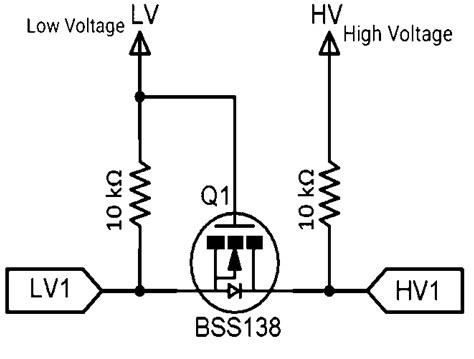
This circuit uses a BSS138 N-channel MOSFET to perform bidirectional logic level shifting between a low-voltage (LV) system (e.g., 3.3V) and a high-voltage (HV) system (e.g., 5V).
Pin Connections:
-
Gate is connected to the LV power supply (e.g., 3.3V).
-
Source is connected to the LV data line (LV1).
-
Drain is connected to the HV data line (HV1).
-
Both sides use 10kΩ pull-up resistors to their respective supply voltages.
Working Principle:
-
When LV1 is high, the gate-source voltage (Vgs) is near 0V → MOSFET is off → HV1 pulled high by resistor.
-
When LV1 is low, Vgs becomes positive (e.g., 3.3V) → MOSFET turns on → HV1 is pulled low through the MOSFET.
-
When HV1 is driven low, it also pulls LV1 low via the MOSFET body diode, which then fully turns on the MOSFET and allows proper low-level transfer.
Usage Notes:
-
LV must be lower than HV for proper operation.
-
Suitable for I²C, UART, and general-purpose bidirectional data lines.
-
Keep the MOSFET’s gate tied to LV to protect it from overvoltage.
Conclusion
The BSS138 is a simple, reliable, and widely used MOSFET for level shifting and low-power switching. With proper voltage levels and pull-up resistors, it can be effectively used in I²C, UART, and general-purpose interfaces between 3.3V and 5V systems.